


9-9-2024: The HVAC&R Weekly Edition: Issue #13
When a 45° offset just ain’t going to cut it. This Issue promises to open up those possibilities. Let’s have some fun.

Welcome back! Were you able to find the key layout dimensions for the 10 inch 38°mitered fitting? Remember the O.D. was 10.750” and you were asked to find the following:
Find the center line Radius (takeoff) for a 10” 90° weld bend = 15”f₂c
Find the OSA→ (Outside Arc-Length) for a 38° mitered fitting from a 90°= 13-1/2” OSA
Find the ISA→ (Inside Arc-Length) for a 38° mitered fitting from a 90°= 6 ⅜” ISA
See the slide below and review the two solutions for OSA and ISA before we move onto locating the two additional Quadrant Marks.
FINDING THE INSIDE AND OUTSIDE ARC-LENGTHS OF A 38° MITERED FITTING
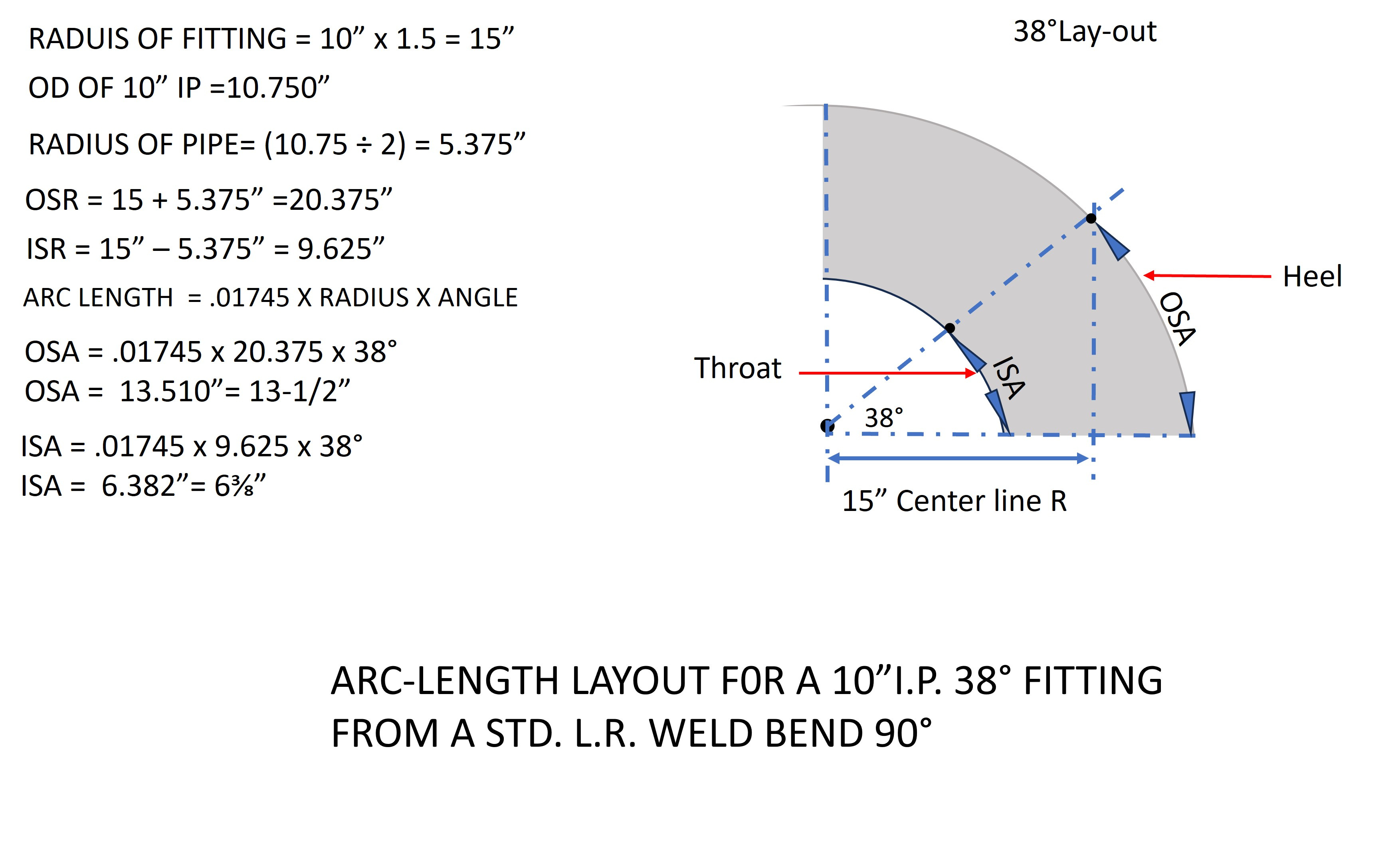
How’d that go for you? I’ve always treated .01745 as any another constant like 1.4142, .707, and .4142 when I worked as a Pipefitter in the field. I use the function key on my scientific calculator Pi (π) ÷ 180° = .01745… to derive the value so I can extract it to 9 decimal places for greater accuracy. You can also use this Arc-length technique to locate the center line intersection point on a pipe header that might require a specific angle of connection to the header.
FINDING A PIPE HEADER INTERSECTION POINT AT 20°
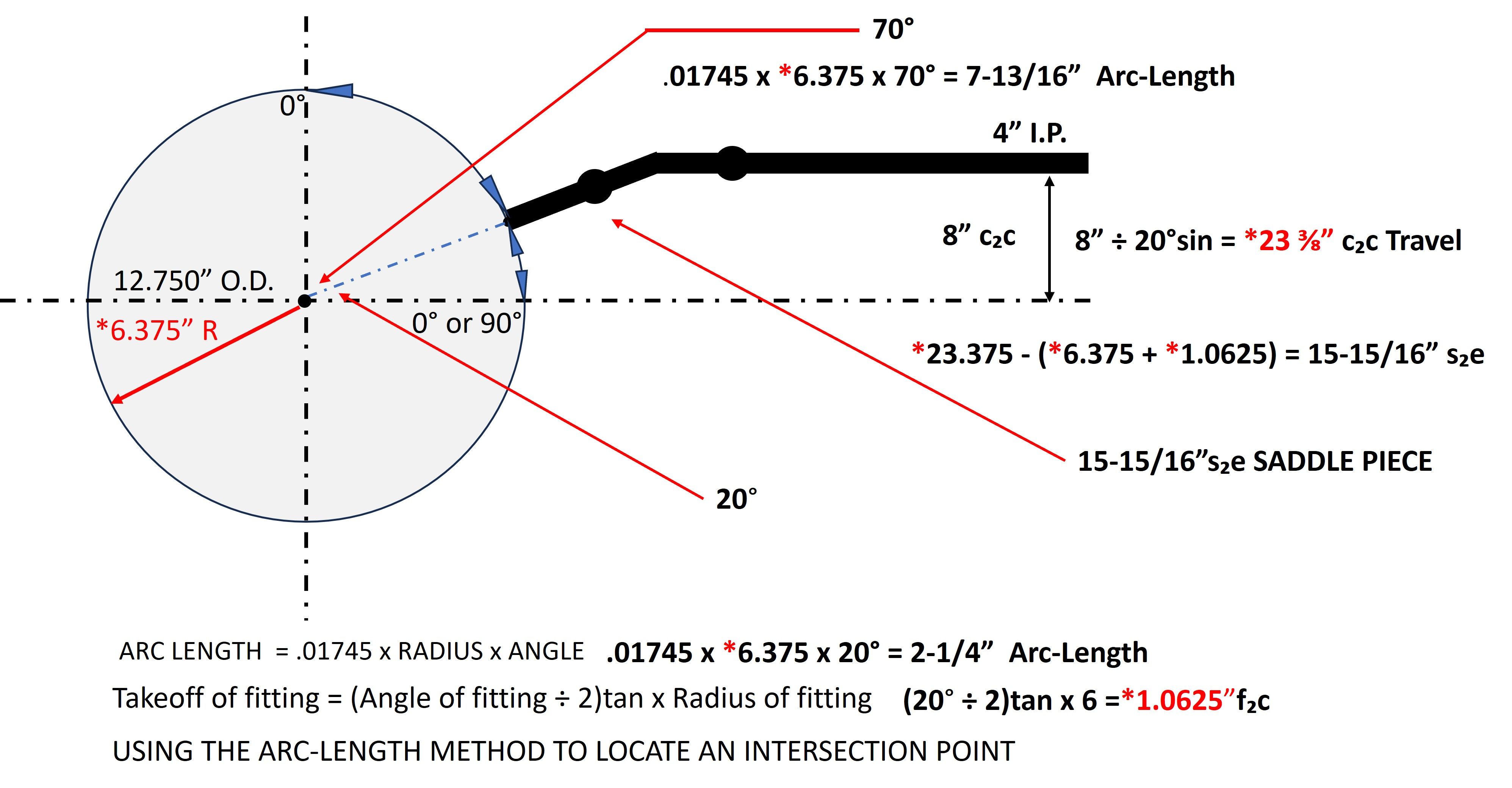
Using this technique requires us to find either the top dead centerline position or a 90°mid centerline position. In the problem above, we located the 20°intersection point up from the 90°mid centerline position. I also located that point down from top dead centerline position at 70° for this example only. In this problem we need a 4” iron pipe saddle coming off a 12” pipe header at 20°. The offset dimension needs to be 8”c₂c up from the 90°mid centerline position. With that information and the Sine Function we are able to determine that the hypotenuse or travel piece needs to be 23 ⅜” center to center. After subtracting 7-7/16” for the radius of the header and the take-off of the 20° fitting we will need a saddle piece 15-15/16”saddle to end. If I was doing this, I would probably install a pair of weld neck flanges and a butterfly valve for isolation in the saddle section. I kind of went off on a tangent there, so back to the original problem.
In the first year of my Apprenticeship I was issued The Pipefitters and Pipe Welders Handbook by Thomas W. Frankland (circa 1940s) a Pipefitter and teacher out of Local 597 Chicago. It was the “Fitters Bible” when it came to anything to do with Pipefitting.
In that handbook they provided the first two steps that I’ve illustrated to find the Heel (OSA) and Throat (ISA) Arc-Lengths, it was cutting edge stuff for me at the time. I felt one short coming in that Handbook was the layout description for locating the Quadrant Marks on either side of the fitting. They suggested using a flexible steel tape laid along the radius of the fitting to locate the Quadrant Marks. It just didn’t seem very practical or accurate. After trying several different procedures I developed the method I introduced to you last week. Let’s review those steps again.
Find the Rise dimension for the Quadrant Mark at 38°→38°sin = 9-1/4” Rise dimension
FINDING THE RISE DIMENSION FOR A 38° MITERED FITTING:
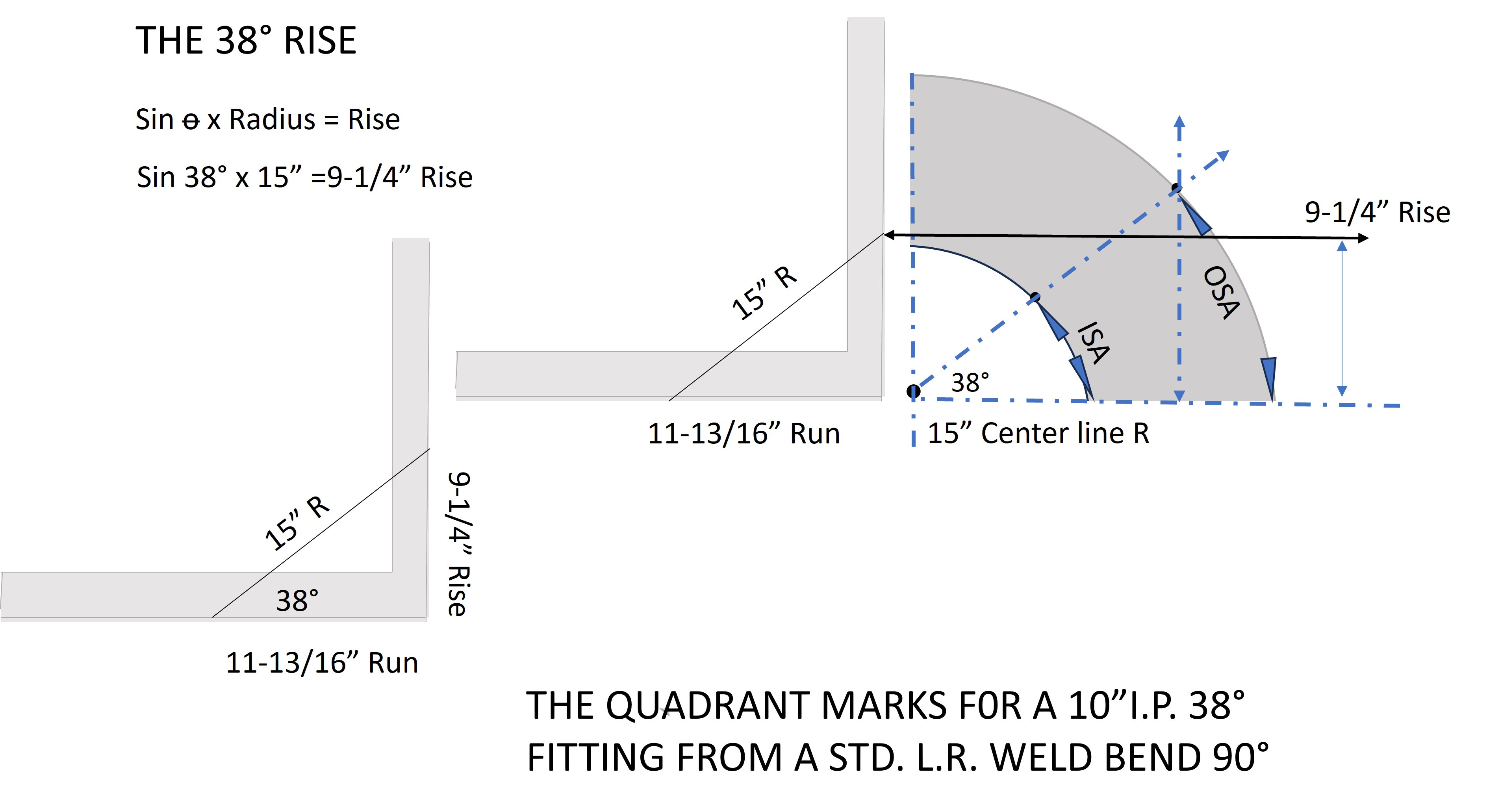
To establish the first Quadrant Mark, position the 90° weld bend so the desired angle is setting on a flat surface. Using the Sine of the angle of the fitting x the radius of the 90° weld bend, calculate the Rise dimension. Use a large framing square or a simple tri-square and mark the Rise dimension vertically on the framing square, then scribe Quadrant Marks on each side of the fitting exactly at the Centerline Radius of the fitting. Make a horizontal mark about an inch long.
Find the Run dimension for the Quadrant Mark at 38°→38°cos = 11-13/16” Run Dimension
FINDING THE RUN DIMENSION FOR A 38° MITERED FITTING:
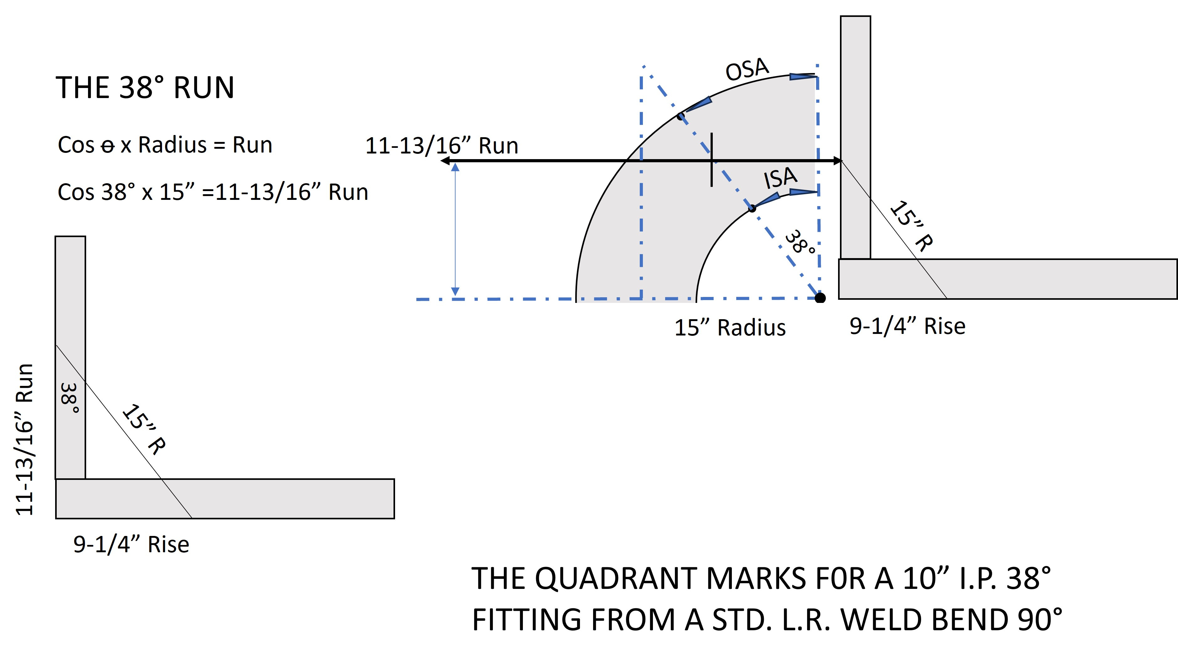
To establish the second Quadrant Mark, flip the 90° weld bend so it sits on the other end. The complimentary angle should be setting on a flat surface. Using the Cosine of the angle of the fitting x the radius of the fitting, calculate the Run dimension. Use your framing square again and mark that dimension vertically on the framing square, then scribe Quadrant Marks on each side of the fitting exactly at the Centerline Radius of the fitting. Making the horizontal mark about an inch long, you should now have four Quadrant Marks, one at the Heel, one at the Throat, and a set of Cross-hairs on each side of the fitting at 38°. The fitting is now ready to be straight cut, faced up with a side grinder, and beveled.
CALCULATING THE TAKE-OFF FOR THE 38° MITERED FITTING
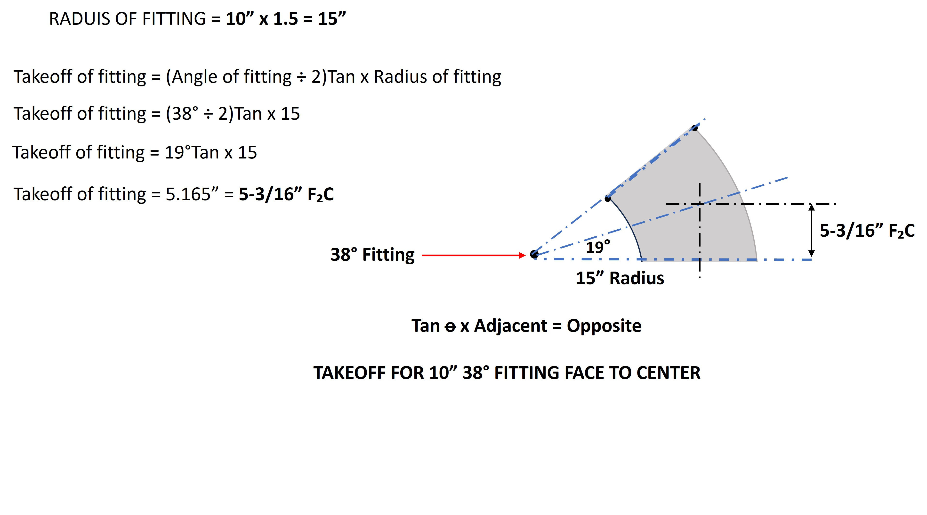
THE ANSWER TO YOUR HOMEWORK CHALLENGE!
Calculate the take-off for the 38°mitered fitting = 5-3/16”F₂C
It would be a good idea to learn the technique for finding the take-off or as some folks state it, the set-back, for an odd angle fitting. Remember to always use 1/2 of the angle of the fitting when making this calculation. Knowing the take-off for a fitting is crucial for determining the proper cut lengths of pipe sections entering or leaving the fitting. It’s also critical for determining the layout of adjoining fabrication pieces containing weld neck flanges or 90°weld bends, as we see below.

THE 45°PERPENDICULAR OFFSET RULE #1 REGARDING WELD BEND FITTINGS
THE GREAT PAYOFF; WHEN PATIENCE BECOMES A VIRTUE
Have you ever repeated a process so many times that it becomes a muscle memory? A very common pipe configuration in the pipefitting industry is a perpendicular 45°offset using two weld bend type fittings. It is when a 45°weld bend fitting is welded directly to a 90° weld bend fitting, it allows the pipefitter to break at 90°perpendicular to the original direction of flow, and change elevation at the same time. It’s one of the many mental muscle executions we commit to memory as fitters. The resulting offset configuration is an offset that is equal to the take-off of the given 90° weld bend when they are a fitting to fitting fit-up and the 90° elbow is rolled at 45°. I call it The 45° Perpendicular Offset Rule #1. For example a 6” I.P. 45°by 90°perpendicular offset would equal a 9”c₂c offset when using two weld bend type fittings as illustrated above.
THE 45° PERPENDICULAR OFFSET RULE #1 EXPANDED
The 45°Perpendicular Offset Rule #1 is our Line In The Sand. We can use it to separate two different types of Perpendicular Offsets that use a 90°weld bend fitting as a component in the configuration. That division point is an offset that is less than 45°degrees, and one that is greater 45°degrees. Here is how we determine that.
PERPENDICULAR OFFSET RULE #2
With The 45°Perpendicular Offset Rule #1 as our reference let me introduce the next offset type.
When a perpendicular offset dimension is less than the take-off of the 90°weld bend fitting of that given pipe size but greater than zero, its offset angle will be less than 45°. We can use this information to generate a formula to find the offset angle needed to produce the required offset dimension. The unknown angle fitting and the 90° weld bend will be fit directly together to produce the required offset dimension. We calculate the value of that unknown angle using this formula below.
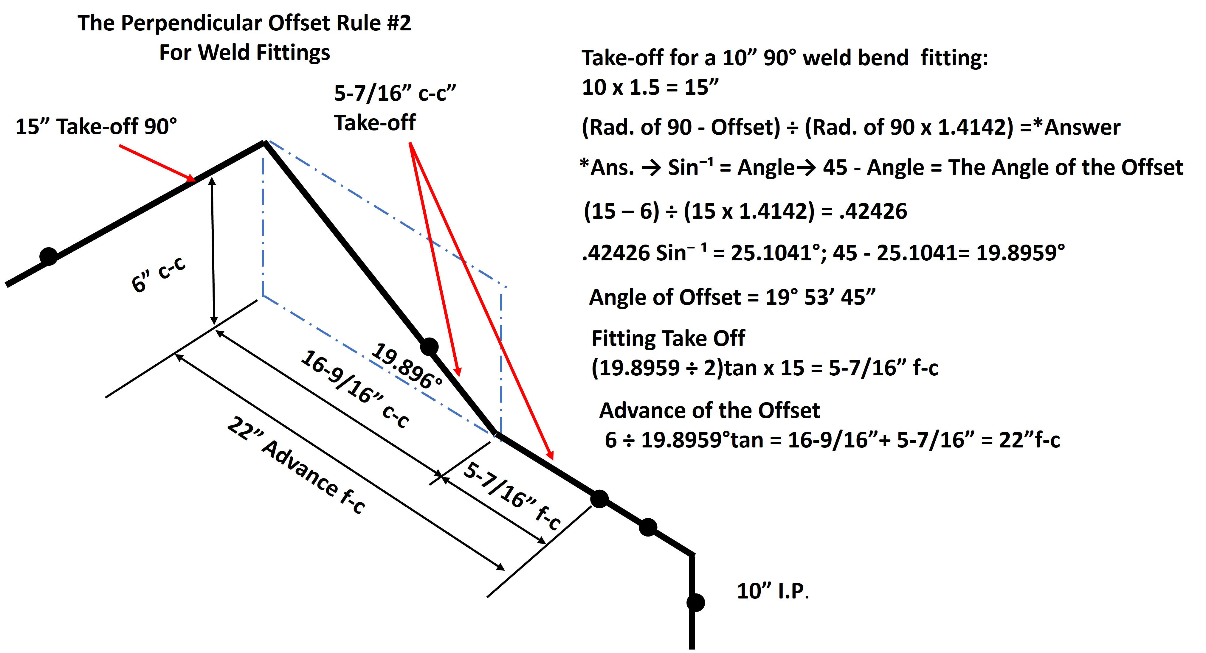
PERPENDICULAR OFFSET FORMULA #2
The offset must be less than the radius of the 90°elbow
Nominal pipe size x 1.5 = 90° fitting Radius
(Rad. of 90° - Offset) ÷ (Rad. of 90° x √2) =*Answer
*Answer → Sin⁻¹ = Angle°→ 45° - Angle°= The Angle of the Offset
Take-off of Fitting = (Angle°÷ 2)tan x Rad. 90° = Fitting Take-Off
Advance of the Offset=(Offset÷Angle°tan)+ Take-off of fitting=Advance of Offset f-c
Proceed with the mitered fitting layout for the angle of the offset
It may seem like a lot to take in at first, but that formula soon became one of my go to items in my tool kit when it came to retrofitting Chillers, pumps, or boilers in existing mechanical rooms. I found that repetition improved my skills and I began looking for opportunities to deploy my new secret weapon. You have to work with what you got and I always tried to make it look esthetically pleasing as well. In this case we solved the problem where a 45°offset would not work by using a 19.896°offset.
PERPENDICULAR OFFSET RULE #3
Think of this Rule #3 as the Yin to the Yang of Perpendicular Offset Rule #2. It provides some balance, the right side of that Line In The Sand. Arguably its use is often more artistic than utilitarian, part of the esthetic nature I was referring to earlier. Although one could argue that when faced with a travel piece 1 ⅜” long, using an 8” 45° perpendicular offset, Perpendicular Offset Formula #3 borders on function over form. One additional advantage for using Perpendicular Offset Formula #3 is that we can reduce the weld count by one.
When a perpendicular offset dimension is greater than the take-off of the 90°weld bend fitting but less than 2 times the take-off of the 90°weld bend fitting of that given size, it’s offset angle will be greater than 45°but less than 90°. We will use this information to generate a formula to find the offset angle needed to produce the required offset dimension. The unknown angled fitting and the 90°weld bend will be fit directly together to produce the required offset dimension. We can calculate the value of that unknown angle using this formula below.
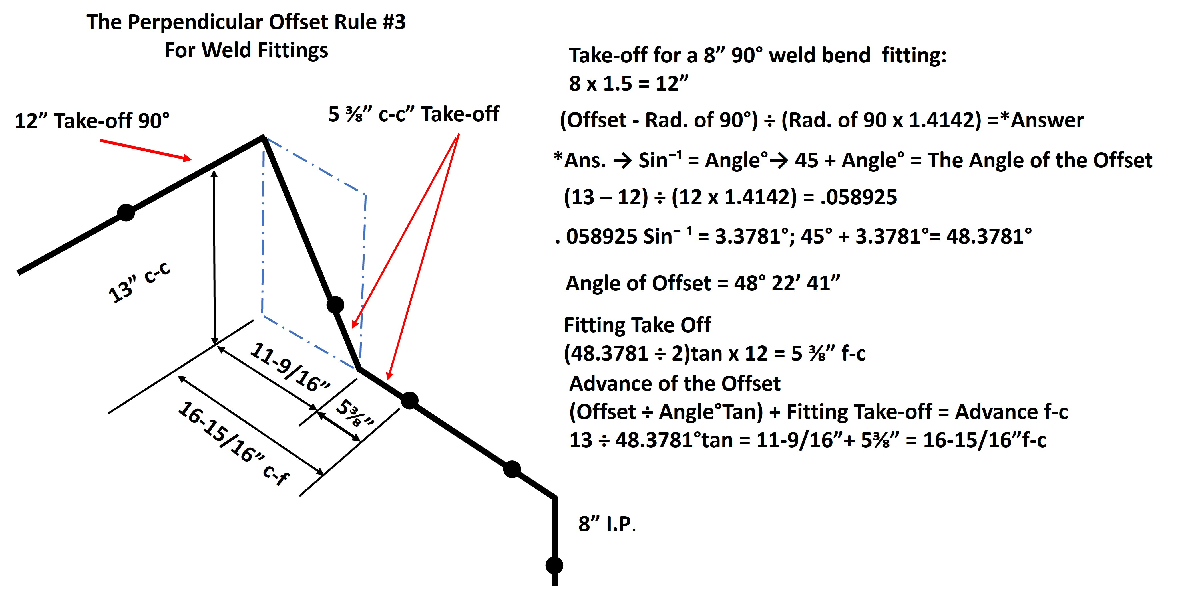
PERPENDICULAR OFFSET FORMULA #3
The offset must be greater than the radius of the 90°elbow.
The offset must be less than the radius of two 90°elbows.
Nominal pipe size x 1.5 = 90° fitting Radius
(Offset - Rad. of 90°) ÷ (Rad. of 90° x √2) =*Answer
*Answer → Sin⁻¹ = Angle°→ 45° + Angle°= The Angle of the Offset
Take-off of Fitting = (Angle°÷ 2)tan x Rad. 90° = Fitting Take-Off
Advance of Offset=(Offset÷Angle°tan)+Take-off of fitting=Advance of Offset f-c
Proceed with the mitered fitting layout for the angle of the offset.
You now have two or three new spells to conjure up from your bag of tricks. With these tools what once was frustrating or seemingly impossible becomes a manageable event when encountering a Chiller, pump, or boiler replacement in which the connection points don’t line up cleanly
PERPENDICULAR OFFSET EXCERCISE PROBLEM:
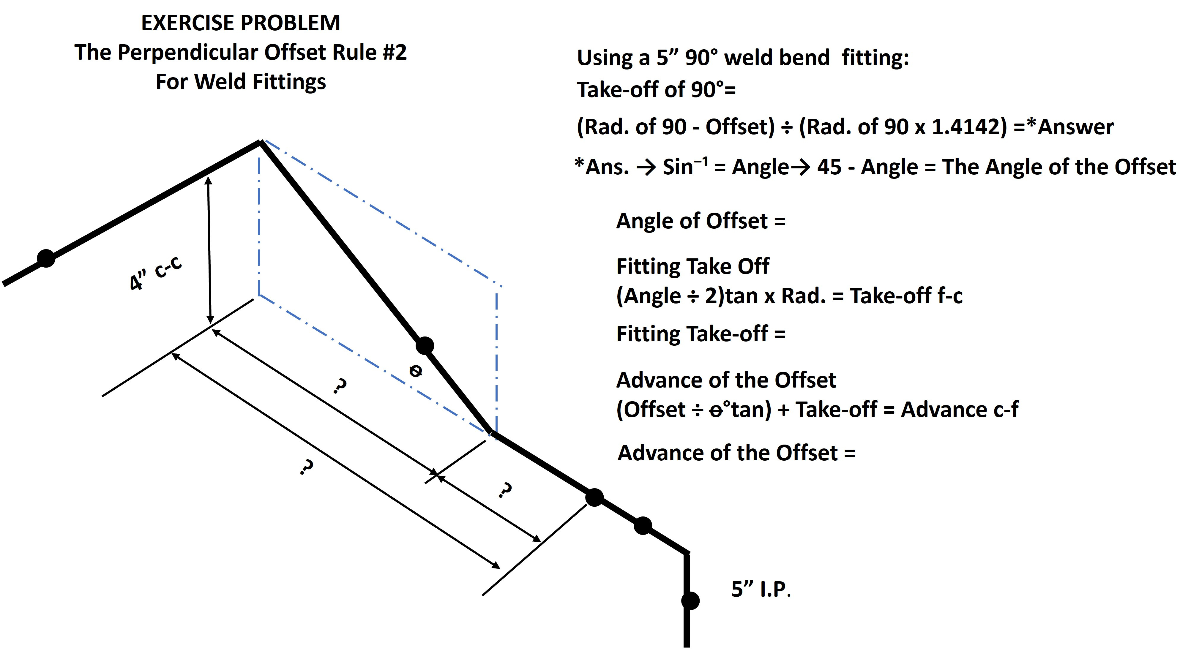
PERPENDICULAR OFFSET EXCERCISE PROBLEM:
Use this Perpendicular Offset Formula #2 to solve and find:
What is the nominal pipe size (see illustration above)
Nominal pipe size x 1.5 = 90° fitting Radius
Note the Offset dimension. It is less than the take-off of the Rad. of one 90°weld bend.
(Rad. of 90° - Offset) ÷ (Rad. of 90° x √2) =*Answer
*Answer → Sin⁻¹ = Angle°→ 45° - Angle°= The Angle of the Offset
Take-off of Fitting = (Angle°÷ 2)tan x Rad. 90° = Fitting Take-Off
Advance of Offset=(Offset÷Angle°tan)+ Take-off of fitting=Advance of Offset f-c
Take-off of 90 weld bend =
Angle of the Offset =
Take-off of the fitting=
Advance of the Offset Center - Face =
Give it a try and we will review that next week. Then we get to drill into two new special Perpendicular Offset Formulas that I developed exclusively for a weld Tee.
I do appreciate your feed back so please leave a comment, or if you have any questions please feel free to reach out. If you know someone that may find this kind of information helpful please feel free to share.
Be safe and have a good week.